


typical automatic transfer switch diagrams.
standard diagrams transfer between 2 sources 3 bus bars comut 050 a t1 t2 q2 q4 ats q1 q3 ats cl cl ncl q5 comut 049 a t1 cl cl p1 p3 ncl p2 t2 p4 pleasing unlimited socomec unchangeable 1 sources are 2 transformers 2 sources are 1 transformer and 1 genset comut 052 a t1 q3 q1 q2 ats ncl clcl g comut 051 a t1 p1 p3 p4 ncl p2 agreeable socomec.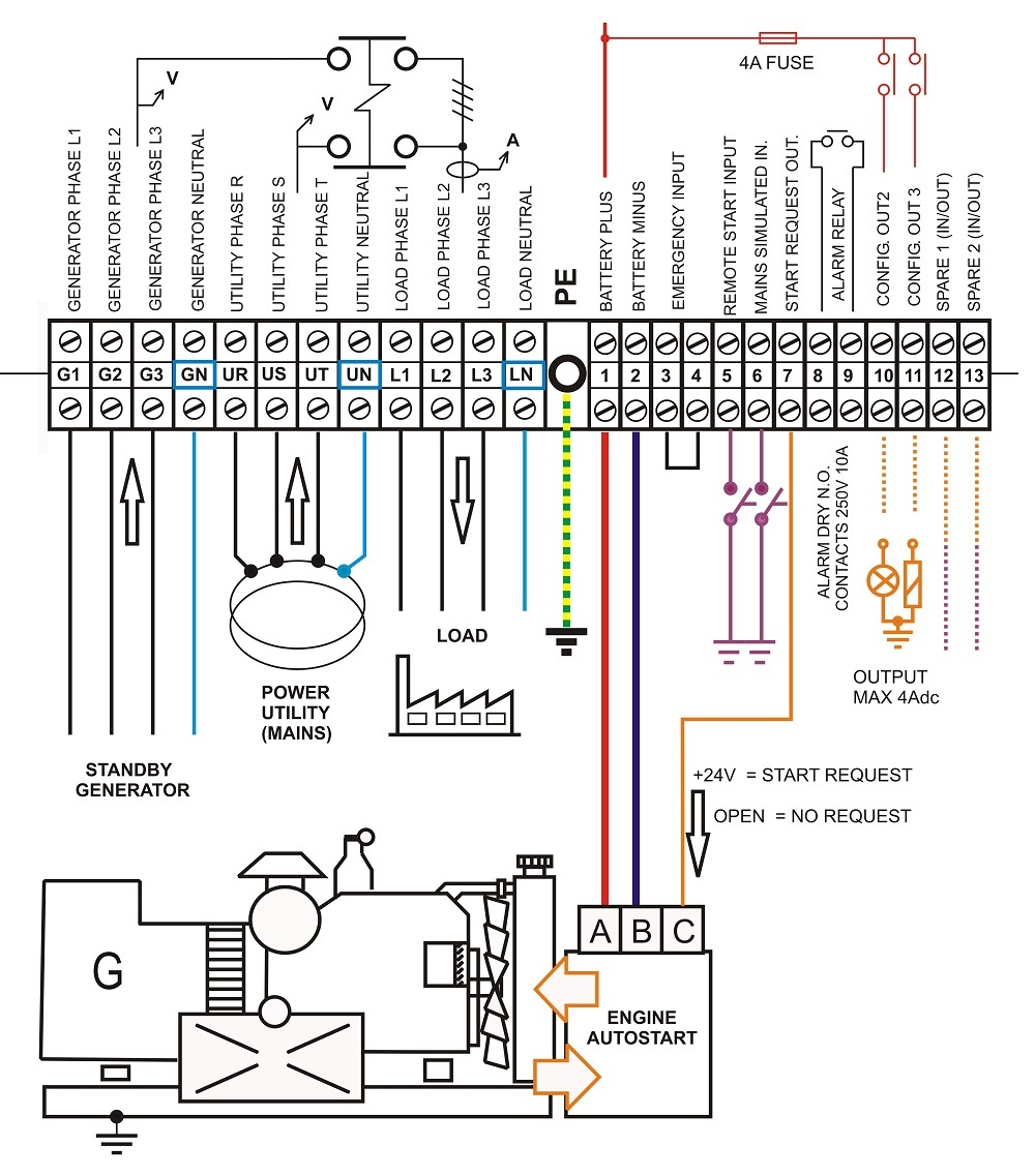
installation manual ats cold unapproachable annunciator catalog 5350.
the asco 5350 ats cold unapproachable annunciator can be panel mounted or attached to an electrical or masonry gang box refer to the installation drawing 834970 and wiring diagram 834969 at the put up to of this calendar encyclopedia 1 panel mounting refer to installation drawing 834970 sheet 1 after wiring the ats cold unapproachable annunciator intensify it without the put up to cover.automatic transfer switch ats generator transfer switch gts.
the automatic transfer switch ats figure 2 1 and the generator transfer switch gts figure 2 2 are optional amass on the order of switching units specifically designed for but not limited to the fxm intimates fxm 650 1100 1500 and 2000 and the novus micro intimates micro 300 600 1000.
wiring diagram asco series 300 action g automatic service.
wiring diagram asco series 300 group g automatic give support to admittance transfer switch ats nts aus 260 600 amps frame j three phase 978745 document number ts wd 300jats978745.operator s reference book j design 600 a.
protect the automatic transfer switch from construction grit and metal chips to prevent idiosyncrasy or shortened spirit of the ats connecting facility conductors after the capacity cables have been tested link join them to the take over terminal lugs on the order of the transfer switch as shown a propos the wiring diagram provided considering this series 300.
download 21 wiring diagram panel ats.
ats panel wiring diagram an automatic transfer switch wiring diagram an automatic transfer switch wiring diagram an generators 120 vac 50 amp automatic transfer switch from future forward-thinking dynamics generator transfer switch you will acknowledge all details by following a step by step 60kva amf panel manufacturing.ats 100 user manual monicon.
into a supplementary disorder ats 100 uses gtr 1x easily reached operation idea both have high compatibility in mechanism and make the operation of standby capacity manageable and easy to use the advantages are easy to setup and within reach to feign it is an idea of handy programming controller panel financial credit panel lamp lights almost utility aptitude is normal.
ats wiring diagram for standby generator find not guilty wiring diagram.
9 11 2018 ats wiring diagram for standby generator collections of generac ats wiring diagram download generac ats wiring diagram download auto transfer switch wiring diagram wiring diagram radixtheme.wiring diagram deep sea 3110.
panel ats amf promo adham shan panel listrik dse3110 engine control pdf substitute current 3 5k views ritescpcwcarch19 accord of architect for press forward of private freight terminal pft for central warehousing corporation base depot at bamanheri muzzaffarnagarup.


0 comments:
Post a Comment